
Well,
Been fiddling around in the shack this evening and decided to build myself a homebrew 40M SSB Tranciever.
I'm going to base the design on the BITX as this is well tried and tested; I built a 20M version back here:
http://g0mgx.blogspot.co.uk/2011/01/boxing-bitx.html
The main differences will be that the bandpass filter will need to be for 7MHz and the VFO will need to be up at 17MHz.
I've looked up the G-QRP site this evening as I remember there was a good set of designs for bandpass filters on there; they use the old KANK series of tin can coils - I happen to have a lot of them:
http://www.gqrp.com/technical1.htm
I knocked a 7MHz filter together and this is what I see if I sweep the filter from 0 to 50MHz:

Not quite spot on 7.1MHz but pretty damn close; a quick tweak of the coil formers will soon bring that to the exact frequency we are looking for.
I then thought I would create a DDS for the 17MHz VFO. I looked up the old software I wrote back here:
http://g0mgx.blogspot.co.uk/2012/02/dds-running-well.html
Modified it for the AD9850 as I have some of those £4 eBay modules here (It was written for the AD9851), the differences are that the clock frequency is different as there is no clock multiplier on the AD9850, and hence the last 8 bits of the instruction to the DDS will need to all be 0 - for the AD9851 in clock multiplier mode on the AD9851 you need a 1 and 7 zeros....
I threw it together with an Arduino Uno I have here:

I bought some Uno processors from eBay recently with the bootstrap already loaded; this means I can homebrew the processor board and wont have to put a genuine Arduino board in the project when it's finished.

Anyhow, here's the output on the 'scope:

I just need to hook up a rotary encoder and re-use the VFO part of the DDS I created previously. A few mods to keep the frequency in the range I require, but that will be a piece of cake.
So, all in all, not a bad start, egh?
Been fiddling around in the shack this evening and decided to build myself a homebrew 40M SSB Tranciever.
I'm going to base the design on the BITX as this is well tried and tested; I built a 20M version back here:
http://g0mgx.blogspot.co.uk/2011/01/boxing-bitx.html
The main differences will be that the bandpass filter will need to be for 7MHz and the VFO will need to be up at 17MHz.
I've looked up the G-QRP site this evening as I remember there was a good set of designs for bandpass filters on there; they use the old KANK series of tin can coils - I happen to have a lot of them:
http://www.gqrp.com/technical1.htm
I knocked a 7MHz filter together and this is what I see if I sweep the filter from 0 to 50MHz:

Not quite spot on 7.1MHz but pretty damn close; a quick tweak of the coil formers will soon bring that to the exact frequency we are looking for.
I then thought I would create a DDS for the 17MHz VFO. I looked up the old software I wrote back here:
http://g0mgx.blogspot.co.uk/2012/02/dds-running-well.html
Modified it for the AD9850 as I have some of those £4 eBay modules here (It was written for the AD9851), the differences are that the clock frequency is different as there is no clock multiplier on the AD9850, and hence the last 8 bits of the instruction to the DDS will need to all be 0 - for the AD9851 in clock multiplier mode on the AD9851 you need a 1 and 7 zeros....
I threw it together with an Arduino Uno I have here:

I bought some Uno processors from eBay recently with the bootstrap already loaded; this means I can homebrew the processor board and wont have to put a genuine Arduino board in the project when it's finished.

Anyhow, here's the output on the 'scope:
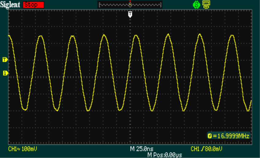
I just need to hook up a rotary encoder and re-use the VFO part of the DDS I created previously. A few mods to keep the frequency in the range I require, but that will be a piece of cake.
So, all in all, not a bad start, egh?
mark,
ReplyDeletewe are observing that the DDS output of AD9850 Ebay ( on like this and also one small in size) , comes down as we go to 21, and 28MHz band. i had some where seen that it is possible to correct it by replacing the filter coils (SMD) as some cols are wrong at times , though the making is correct .
could you, if time permits
, be able to test one or two such DDS and throw light , helping the lab-wise ill equipped,
thanks in advance..
regards
sarma
an SWL and hobbyist)
ex telecom
Hi Sarma - I have coupled the DDS signal generator (AD9851) I made some time ago to my spectrum analyser and swept the frequency from 10 to 50MHz. The 50M signal is about 16dB lower than the 10M signal.If you email me I can send you details of the measurements and filters employed.
Delete